computer controlled PID-regulator

|
An inverted pendulum on a chart with
computer controlled PID-regulator |
|
Back to Stefan's Some technical projects page
Report by Stefan Spännare September 10 2018. Latest update Mars 16 2019. To be updated
1. Introduction
2. Summary of technical components and software
3. Computer program downloads and instructions
4. Some photos and videos of the inverted pendulum
5. References
Here is a description with photos and video of a quite well working inverted
pendulum on a chart with computer controlled PID-regulator. More detailed
description will come with schematics and software download.
November 8 2018. I am right now experimenting with a simple Furuta inverted
pendulum with the same PID-regulator software and schematics. Some images
are now avalable below.
Mars 16 2019. With some software modifications the setup works also as a drive for
low speed DC servo motors with encoder. The software however must be developed futher
to work well.
New!
February 6 2020. I have now made a much better solution for the servomotor software.
However some issues regarding encoder reading still remains. Probably due to speed.
Tentative test software with documentation and schematics will come.
Section to come soon.
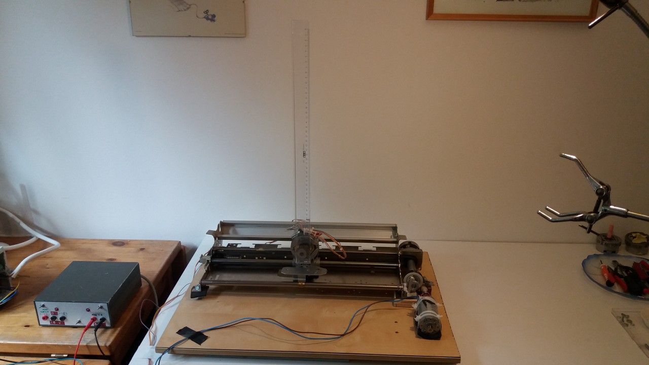
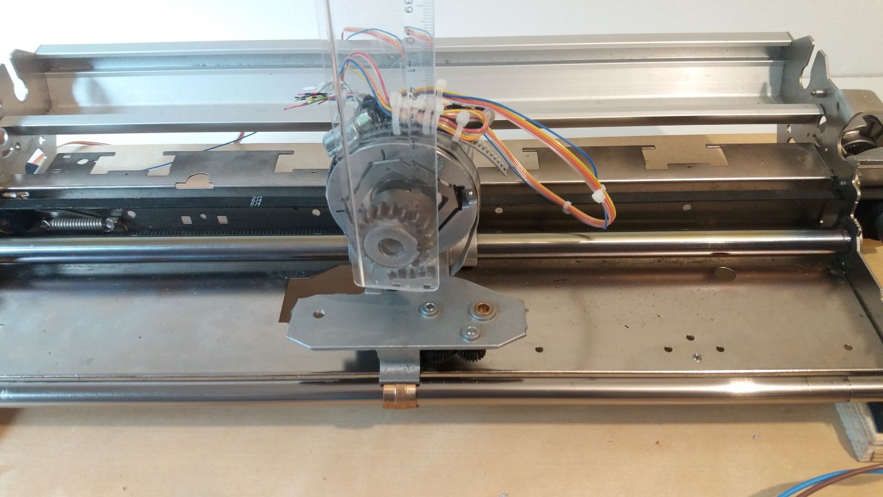
Some photos of the inverted pendulum with electronics taken with my mobile.
More information and images to come soon.
|
|
|
|
|

|
A video of the inverted pendulum taken with my mobile. It works quite well,
but as you understand I wish the track on which the chart is running was at
least two times longer. More information to come soon.
inv-pend-video1.mp4 (Full HD 247 MB, 120 seconds long)
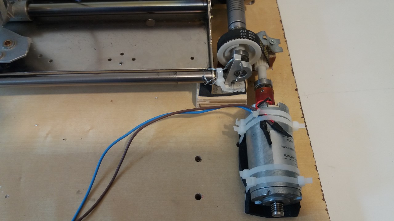
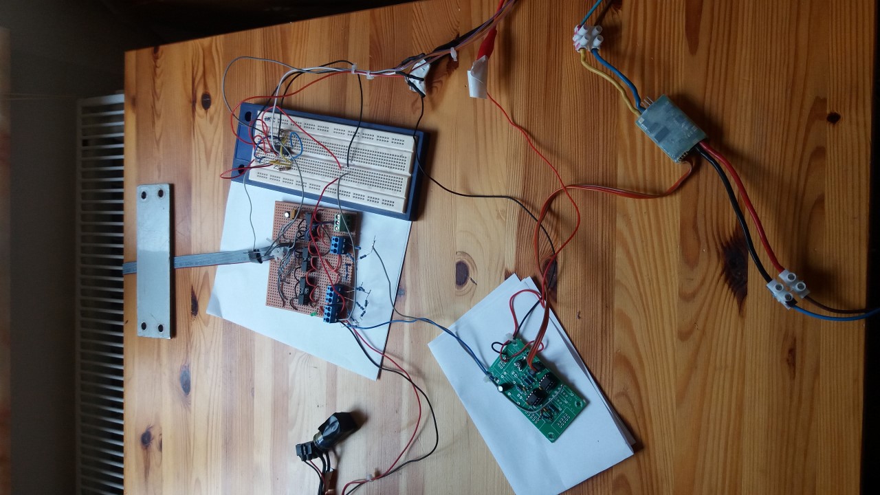
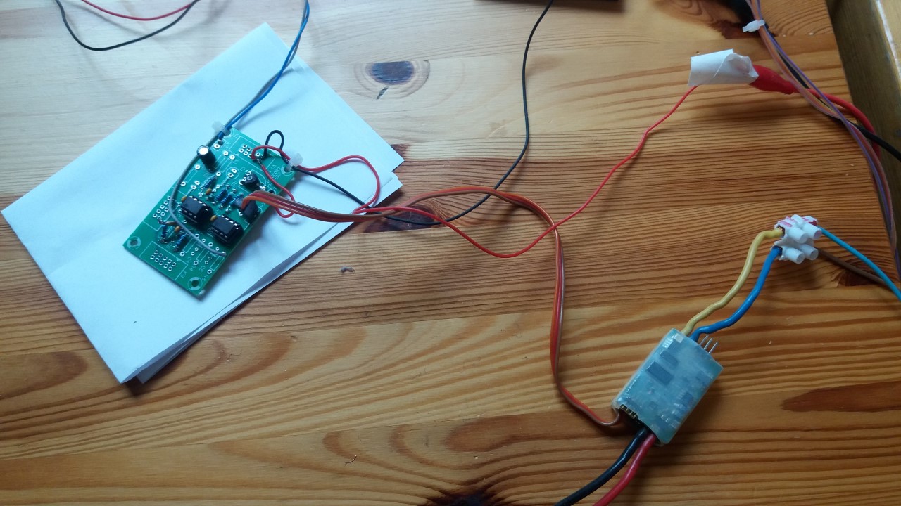
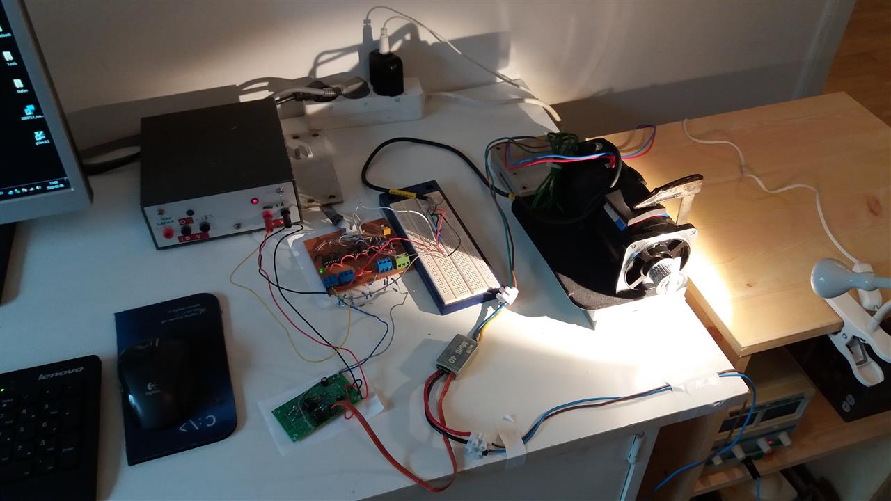
Some photos of the DC servo motor setup with the electronics taken with my mobile.
The servo motor is a nice Sanyo Denki, 32 V, 250 W, 3000 rpm with encoder with
400 steps per rewind. This means 1600 steps per rewind with sinusoidal outputs.
|

|

|
A video of the servo motor running (here at 10 V DC) taken with my mobile. 50 positions
randomly 4 to 10 rewinds in each direction. Perhaps this looks quite ok? But the stop criterion
(when the motor reach a certain position) must be improved and perhaps more important
the sampling frequency for the encoder must be much higher. Perhaps I will implement
the PID steering program in a fast micro controller (with floating point operations and digital
I/O ports)? Time will tell when. At present (on the PC 3 GHz with the PCI-DIO024 I/O card)
the sampling rate of the encoder is about 66000 times per second and it sometimes misses
some step readings.
servo-motor-video1.mp4 (121 MB, 60 seconds long)
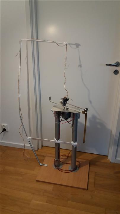
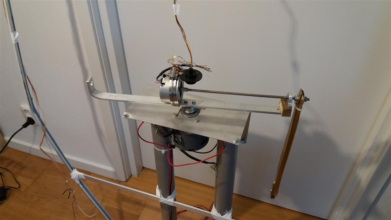
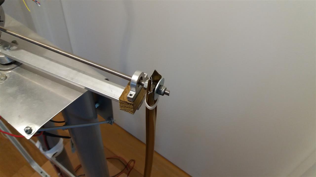
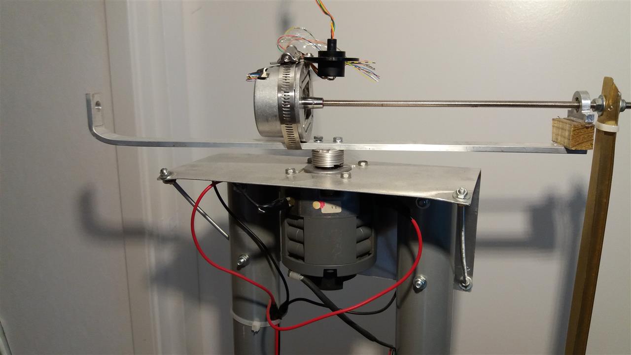
Some photos of the Furuta pendulum not connected to the electronics and PID regulator.
The photos are taken with my mobile. The Furuta pendulum seems significantly more
difficult to balance with the PID regulator setup than the pendulum on a chart. I hope
I can present a video here soon. The Furuta pendulum has a low speed high torque direct
driven DC motor (about 800 rpm at 12 V) and a device so the cables to the encoder on
the pendulum bar can rotate freely. The encoder is a Heidenhain ECN 1313 with 2048
steps per rewind (8192 with sinusoidal outputs).
|
|

|
|
|
ELFA A nice electronics component shop in Sweden
JoR Measurement A place to buy very good I/O cards for PC and much more in Sweden
Microsoft Visual Studio Community 2017
A very good and free programming environment with with C/C++ and many other languages