i. Warning
The author makes no warranties that this document is free of errors. Please read
it through carefully as a whole before starting to build the power supply. Se also
"Important notice" below. This project is only recommended for experienced
electronics hobbyists.
1. Introduction
A good power supply is one of the first things the electronics hobbyist wishes to
have in the lab. The power supply described here has good data an can handle a
little higher currents that is usual for most power supplies found in the
electronics literature. The circuit layout of the power supply is based on articles
found in data sheets, electronic books and elsewhere on Internet (see the
references). It should however be mentioned that it is not much cheaper to build
this power supply than to buy one with comparable data. But it is very fun to
build!
2. Power supply data
Here are presented some data for the power supply.
| Voltage range: | 2 - 24 V (max 30 V) |
| Max current: |
10 A (2 - 15 V),
15 A (15 - 24 V), < 5 A (24 - 30 V) |
| Current limitation range: | 4.2 - 18 A |
| Max voltage drift: | 30 mV |
| Max ripple: | 10 mV |
| Max power dissipation: | 300 W (with heatsink and fans) |
| Fuse, DC output: | ≤ 15 A (fast) |
| Fuse, mains voltage: | 4 A (slow) |
| Mains voltage: | 220 - 230 V, 50 Hz |
The transformer and rectifier part:
The regulator part
Here are presented four different regulator circuits (A - D) for the power
supply. With or without current limitation. The author use version C. The
first two are not recommended.
It should be noted that if the power supply is short circuited with a power
limitation of 10 A or more very much power (heat) is dissipated from the
transistors (200 - 300 W). This can destroy the transistors. Always use
a secondary fuse of 10 or 15 A (or smaller) before the regulator part.
The circuit layouts below have also been updated with a capacitor of 100 pF
and the capacitor of 680 pF has been removed.
A. Regulator part with no current limitation:
This circuit is not recommended to use because of no current limitation.
B. Regulator part with old current limitation:
This circuit is not recommended to use because risk of thermal runaway
in the transistors. The "current sense" is measured over the base-emitter
connections of the power transistors (and also the power resistors). The
hFE in the transistors (and thus the current) increases with temperature.
C. Regulator part with variable current limitation (4.2 - 18 A):
This is the current limitation now used by the author. It has no thermal run-
away problem. The "current sense" is measured over a thermally stable power
resistor. The voltage drop over this 0.15 Ohm, 50 W resistor is 2.25 V at 15 A
current. This means that the total voltage loss over the power transistors and
power resistors is so large that the maximum current can not be larger than
14.5 A at 24 V output voltage. A transformer with 30 V secondary (instead of
28 V) would remedy this. But then the LM 723 circuit and the main rectifier
capacitor would be stressed. They have "absolute maximum ratings" of 40 V.
The rectified idle voltage from the transformer part is about 38.5 V with
a 28 V secondary and 2 V more is too much.
D. Regulator part with fix current limitation (18 A):
This circuit has a fix current limitation of about 18 A (see the references).
It has no thermal runaway problem. The voltage drop over the two 0.1 Ohm,
10 W resistors is 0.75 V at 15 A current. The "current sense" is measured
over these resistors.
Thermostat and fan driver:
4. Dimensioning
This power supply use a 500 VA toroid transformer with 28 V secondary. Thusthe maximum output current is 500 VA / 28 V = 17.86 A. Because the voltage is
rectified and filtered (with a large capacitor) it is probably more correct to divide
with the DC voltage (sqrt(2) * 28 V = 39.60 V). Then the maximum current
becomes 500 VA / 39.60 V = 12.63 A. For intermittent use it would be safe to
say that the maximum allowed current is 15 A (and use a fast fuse of maximum
15 A).
For the mains voltage (220 V) a slow 4 A fuse must be used. The high value is
needed because of the high transient current spike when the (500 VA)
transformer is turned on. The author tested a 3.4 A slow fuse, but it was broken.
It should be pointed out that it is waste of heat and power to use a transformer
with much higher secondary voltage than required. If you for example know that
your maximum output voltage is 15 V it is better to use a transformer with say
18 V secondary. In general the transformer secondary AC voltage should be 3 V
to 5 V higher than the maximum desired DC voltage. This also minimizes the
size of the transformer and the heatsink. It should also be mentioned that the
minimum operating voltage for the LM 723 voltage regulator circuit is 9.5 V.
The maximum operating voltage for the LM 723 circuit is 40 V, why a
transformer with not higher than 28 V AC secondary (39.60 V DC) must be
used.
In the regulator part it is recommended to have at least one 2N 3055 transistor
and one 0.1 Ohm resistor per 5 A output current. Thus at least 3 of each at an
output current of 15 A. If we assume that the maximum power dissipation in the
3 transistors is 300 W a heatsink better than 1.5 °C/W is recommended. Actually
the 2N 3055 transistors survives 115 W and 15 A each at most with optimal
cooling. Note, that fans are absolutely necessary for higher output currents! If
for example the output voltage is 16 V and the output current 15 A the power
dissipation in the transistors will be (32 � 16) V * 15 A = 240 W. The rectified a
filtrated voltage is here assumed to be 32 V at this current. This means that the
temperature of the heatsink will increase with 1.5 °C/W * 240 W = 360 °C without
fans! This will immediately destroy the transistors. This is also the reason why
currents above 10 A is not recommended for output voltage less than 15 V
(unless the transformer secondary voltage is reduced). It is a good idea to switch
the fans on and off with a thermostat when the heatsink reach a temperature of
say 70 °C.
The BD 243 C transistor survives a current of at maximum 6 A and feeds the
base current to the 2N 3055 transistors. The 2N 3055 transistors have a current
amplification (hFE) of at minimum 15 at 5 A current. Thus the "Darlington"
coupling can handle 15 * 6 A = 90 A, which is well above the desired 15 A
output current. Note that also the BD 234 C transistor need some cooling and
must be mounted on the heatsink. The maximum output current from the LM
723 voltage regulator circuit is 150 mA. The minimum current amplification
(hFE) for the BD 243 C transistor is also around 15 at 3 A current. Thus the
maximum regulated output current can be 15 * 15 * 0.15 A = 33.75 A, which
also is well above the desired 15 A. If higher output current is needed the BD
243 C transistor can be replaced with a transistor with higher current
amplification (hFE). But then also more 2N 3055 transistors are needed.
The rectifier must also survive the maximum current. At minimum a 25 A
rectifier is recommended. Because there is a voltage drop of about 2 V over the
rectifier it must have a relatively large heatsink (2 °C/W) to cool away 2 V * 15
A = 30 W at maximum. No fans are needed here.
It is recommended to use at least 4700 uF filter capacitor per Ampere output
current. The author use a 100000 uF (40 V) capacitor for a maximum output
current of 15 A, which is more than needed.
5. Current limitation
In the circuit layouts in section 3 are now presented some different solutions
to the problem discussed below. See also the references.
The maximum output current can be adjusted by a 10 revolution 1kOhm
potentiometer. However this circuit has one large disadvantage. The set current
limitation is not completely stable, but varies somewhat with the temperature of
the transistors. For higher currents the limited value tends to increase somewhat
(20 %) when the transistors get warmer. Thus the circuit is not a perfect constant
current generator. But still it can be used to protect the load from being
destroyed. It is however somewhat dangerous to use current limitation at high
currents because the main transistors can be destroyed due to thermal
breakdown. If we set the maximum current to 12 A and then short circuit the
output, the power dissipation in the man transistors will be 32 V * 12 A = 384
W, which will probably destroy them. It is important to not only rely on the
current limitation, but also use as small secondary fuse as possible to save your
load (and the power supply).
For those who are technically interested it can be mentioned that the current
limitation would work better (be less temperature sensitive) if the "current sense
pin" (CS) on LM 723 could be connected only over the 0.1 Ohm resistors (not
over the two base-emitters of the transistors as well). However then the voltage
will not be high enough over the positive voltage output (0.7 is V required) to
make current limitation possible. The maximum voltage over the resistors is (0.1
/ 3) Ohm * 15 A = 0.50 V at 15 A load. The total base-emitter voltage drop of
the "Darlington" transistor coupling is about (0.7 + 0.7) V = 1.4 V.
Unfortunately this value is not stable with temperature. This means that the
voltage over CS can be varied with the 1kOhm potentiometer from 0 V to (1.4 +
0.5) V = 1.9 V which is well above the required 0.7 V. One solution would be to
make the resistors larger (and connect CS directly over them) but that would
increase the voltage drop and power dissipation over the resistors which is
unsuitably at this high currents. If you have a better solution how to make a
good current limitation please send an email to the author!
6. Building instructions
The power supply is divided in two parts, the transformer part and the regulator
part. The reason for this is that the transformer part is so heavy and difficult to
move. The construction can best be seen from the photos below. The two parts
are connected with a 1.5 m cable with an area of 4 mm². All the connections in
the transformer part on the secondary side (to the rectifier, main capacitor and
output terminals) are also made with 4 mm² cables. The two 28 V secondary
windings of the transformer are connected in parallel. The low current parts of
the regulator are made on a standard laboratory card. As seen from the photos
the regulator part is an open construction. This is because it is an experimental
setup. The author recommend very much to use a closed plastic or glass fiber box
with appropriate holes for the ventilation (the heatsink and the fans). It is also
recommended to isolate the main transistors from the heatsink to avoid short
circuit by accident (although it was not done by the author). The transformer part
should be built in a large plastic or glass fiber box. If a metallic box is used don't
forget to ground it carefully. For the output power terminals 4 mm "banana plugs"
(males and females) of good quality are used. The fans are two standard 80 mm,
12 V computer fans powered from a separate 7812 voltage regulator. The fan
thermostat is also powered from the 7812 regulator. The 7812 regulator must have
a small heatsink of its own. The thermostat sensor is directly in thermal contact
with the heatsink. It is however important to isolate the sensor electrically from
the heatsink. Such thermostats can be bought from the companies "ELFA" and
"Kjell & Company" in Sweden (see the references).
7. Important notice
The author apologies for being nagging, but here are some important notes. The
power supply must be carefully assembled. Do absolutely not omit the fuses. Be
very careful when connecting the 220 V parts. The transformer case and box
must be carefully grounded. Use a good heatsink for the main transistors. It is
absolutely necessary to cool the heatsink with fans for high current outputs.
Use high quality components. Be very careful when soldering the components
to avoid short circuit. Be very careful to not reverse the polarity of the main
capacitor. It is very important to connect the two secondary windings of the
transformer in parallel with the same phase. A transformer of this size is
not that fun to short circuit.
8. Electronic component data
Here are presented some data (absolute maximum ratings) and approximate
prices for the most critical components in the power supply. Imax and Pmax
are given with appropriate heatsinks. The components can preferably be
bought from the company ELFA in Sweden (see the references). The total
price for the power supply is about $ 250 (including VAT) in Sweden.
It is probably somewhat cheaper elsewhere.
| Component | Umax (V) | Imax (A) | Pmax (W) | Price ($) |
| Transistor 2N 3055 | 60 | 15 | 115 | 2 |
| Transistor BD 243 C | 100 | 6 | 65 | 1 |
| Diode LT10A04 | 400 | 10 | 10 | 1 |
| Rectifier FB5006 | 600 | 50 | 100 | 7 |
| Resistor 0.1 Ohm | 1 | 10 | 10 | 1 |
| Resistor 0.15 Ohm | 2.74 | 18.25 | 50 | 4 |
| Voltage regulator LM 723 | 40 | 0.15 | 0.6 | 1 |
Here are approximate prices for the most expensive parts of the power supply.
| Component | Data | Price ($) |
| Transformer | 500 VA, 2 x 28 V | 60 |
| Capacitor | 100000 uF, 40 V | 30 |
| Potentiometer |
1 k and 20 k, 10 revolution, thread winded | 10 |
| Heatsink | 1.5 °C/W | 15 |
| Fan | 80 mm, 12 V | 10 |
| Thermostat | 12 V | 10 |
| Box |
For the transformer part and the regulator part | 20 |
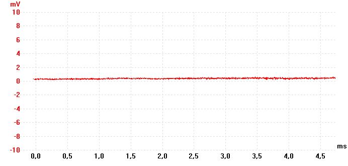
9. Some oscilloscope views
These images are taken with a Pico Technology ADC-212/3 oscilloscope for PC.
The PWM pulsed load was used as a difficult test for the power supply.
1. Power supply ripple at 18 V without load and fans turned off.
2. Power supply ripple at 18 V and 13 A resistive load with fans turned off.
PWM pulse at 100 % duty cycle (voltage always turned on).
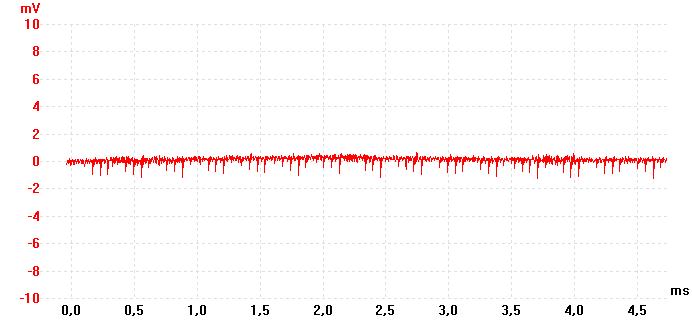
3. Power supply ripple at 18 V and 13 A resistive load with fans turned on.
PWM pulse at 100 % duty cycle (voltage always turned on). The fans
introduce some extra noise spikes.
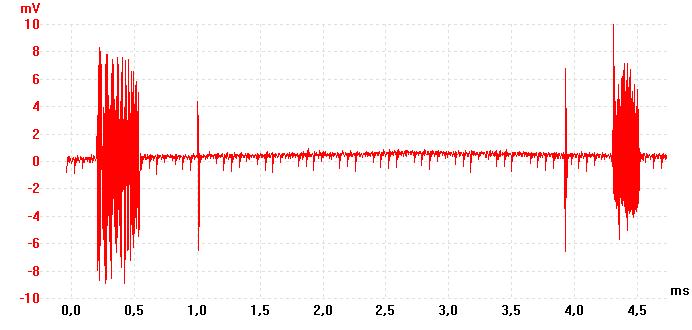
4. Power supply "ripple" at 18 V and 13 A resistive load switched on and off at
488 Hz and fans turned on. PWM pulse at 50 % duty cycle. The heavy switched
load introduce some quite large spikes at the power supply voltage. Perhaps also
the current limitation at 18 A of the power supply is activated for a very short
time during the pulses.
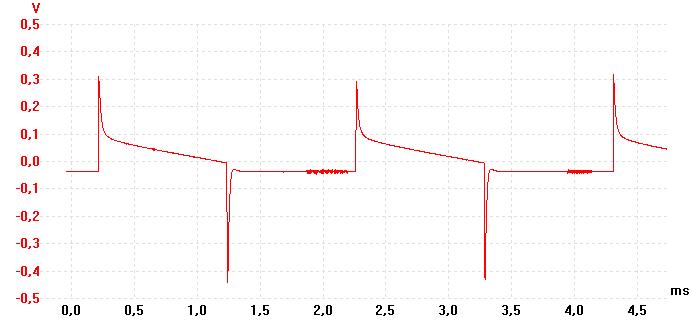
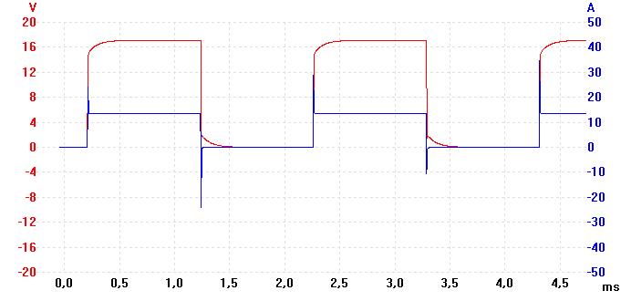
5. The test signal at 18 V and 13 A resistive load switched at 488 Hz with a fast
MOSFET transistor. PWM pulse at 50 % duty cycle. The load was a thread-winded
water-cooled resistor at 1.4 Ohm. The current was obtained by measuring the voltage
over a 0.1 Ohm, 10 W resistor connected in series with the load resistor.
10. Some images (photos)
Here are now presented some new images with the updated current limitation.
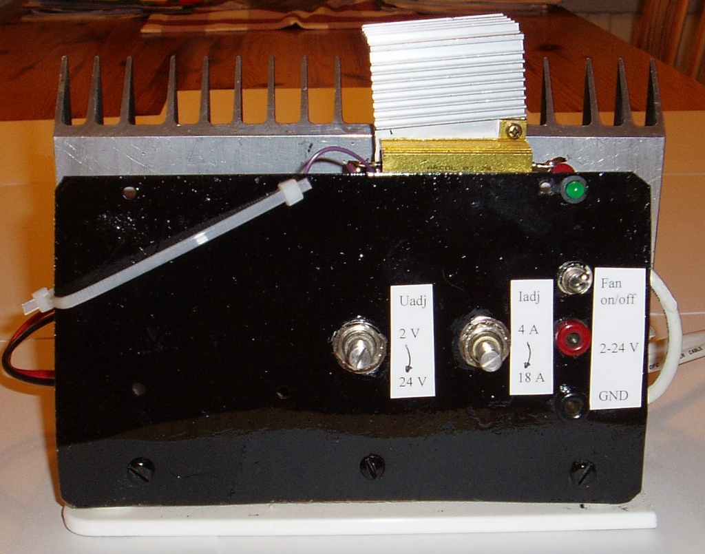
1. The front panel of the regulator part. The Uadj and Iadj potentiometers
now have rotation directions according to standard.
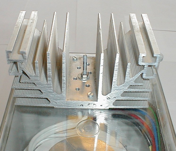
2. The regulator part seen from above. Note the 0.15 Ohm, 50 W
resistor (with a small extra heatsink) for the current limitation.
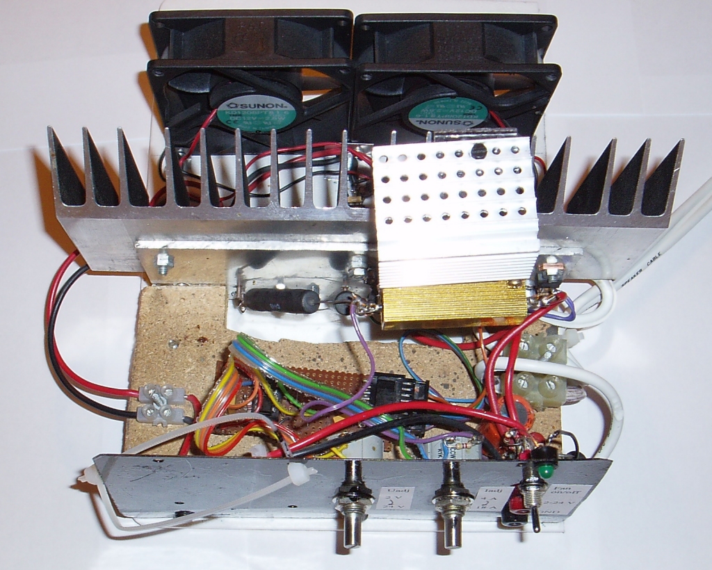
3. Another view of the regulator part seen from above.
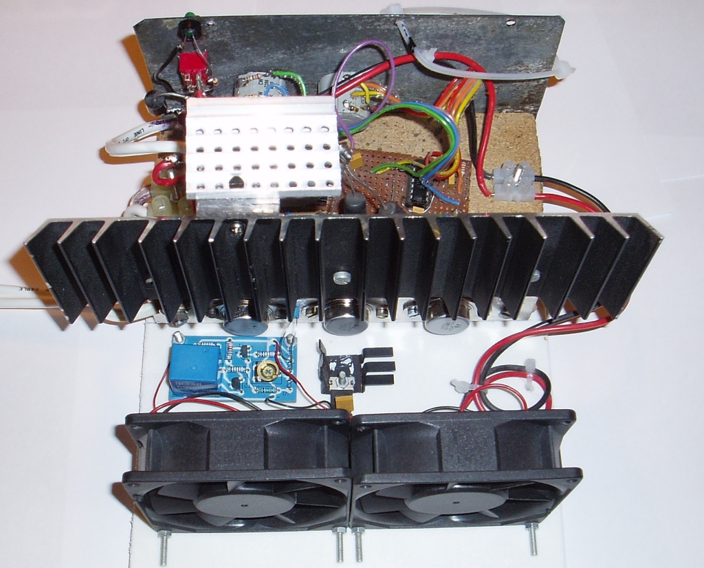
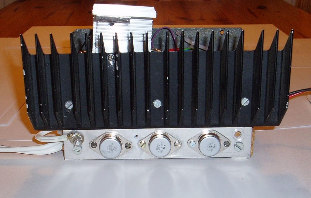
4. The main transistors (2N 3055) with the heatsink.
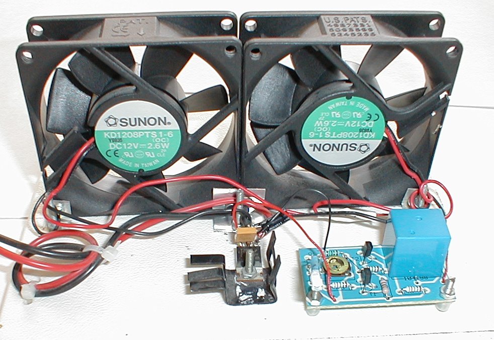
5. The fans, the thermostat and the 7812 voltage regulator.
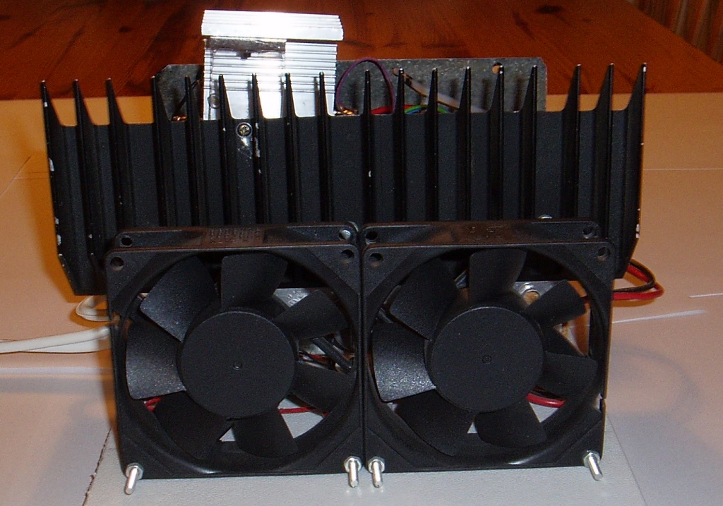
6. The fans and the heatsink.
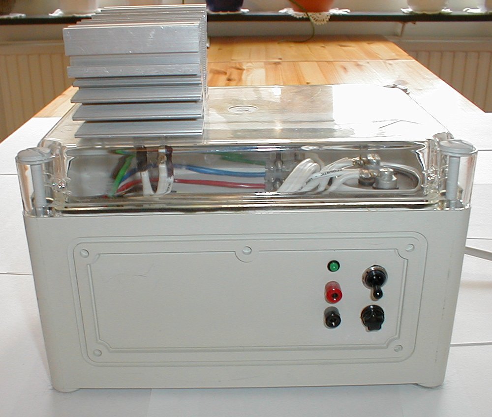
7. The transformer box with the rectifier heatsink above.
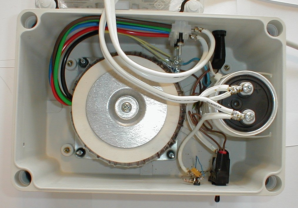
8. The transformer and the main capacitor seen from above.
9. The cable connections to the rectifier.
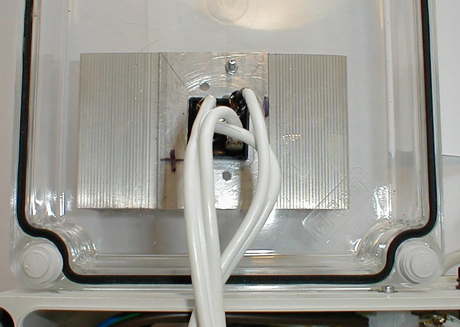
10. The rectifier heatsink.
11. References
Some useful data sheets (mostly from ELFA) to download:
- 2n3055.pdf (49 kbyte), "2N 3055, Transistor", by ST, August 1999
- bd243c.pdf (35 kbyte), "BD 243 C, Transistor", by ST, September 1999
- lt10a04.pdf (71 kbyte), "LT10A04, Diode"
-
lm723.pdf
(261 kbyte), "LM 723, Voltage Regulator",
by National Semiconductor, December 1994
Some useful Internet links:
- Build A 10 Amp 13.8 Volt Power Supply
- ELFA A nice electronics component shop in Sweden
- Kjell & Company
- Pico Technology
- L.A.N.Z.O Sweden AB
Author: Stefan Spännare
E-mail: stefan@NOspaennareSPAM.se (Please remove NO and SPAM before sending)
Latest update: 2008-09-29